Assessing and Restoring a MEEP System in Sintering Operations: Key Structural Insights and Retrofit Strategies
Summary
Moving Electrode Electrostatic Precipitators (MEEP) are widely used in sintering processes across the steel industry. This article draws on the inspection and retrofit of a 360m² MEEP system that had been in continuous operation for over a decade. We analyze how structural components—particularly the moving electrodes and rapping mechanisms—affect performance, and offer practical insights into executing a high-efficiency retrofit under tight time and supply constraints.
1. How MEEP Systems Work and Why Structure Matters
The MEEP operates by generating an electric field via discharge electrodes (cathode wires), which charges dust particles in the flue gas and drives them toward the collecting electrodes (anode plates). Unlike conventional fixed-plate ESPs, the MEEP’s collecting plates move periodically, shedding accumulated dust without mechanical rapping. This continuous self-cleaning motion makes the MEEP particularly suited to sintering gas with fine, sticky, and high-resistivity particulates.
However, the performance of a MEEP system is highly dependent on the mechanical integrity and motion stability of its electrode assemblies. Issues like plate misalignment, jamming, or mechanical wear can disrupt electric field uniformity and inhibit voltage build-up, leading to inefficient particle capture and inconsistent emissions.
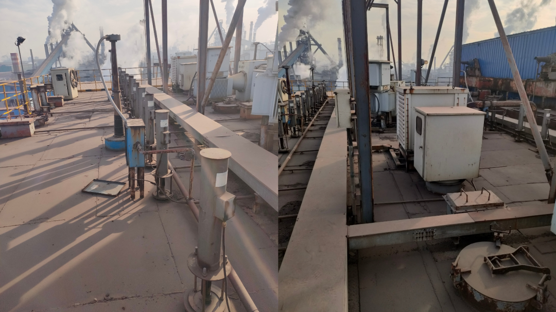
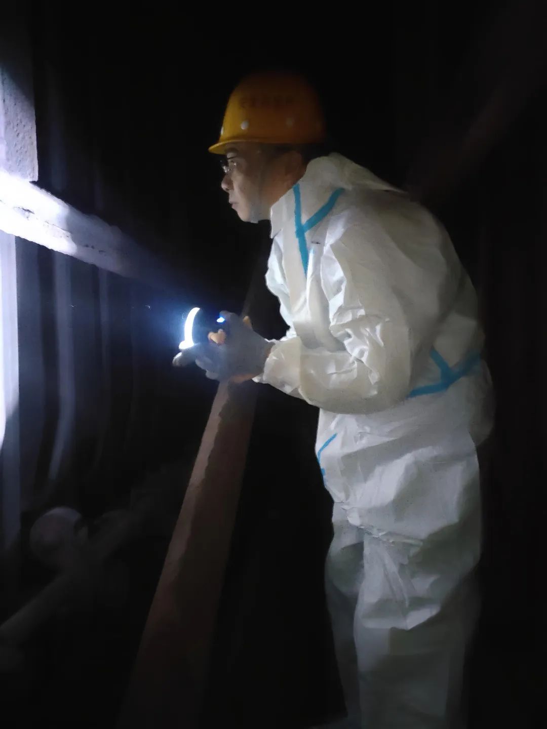
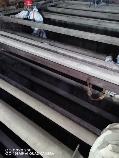
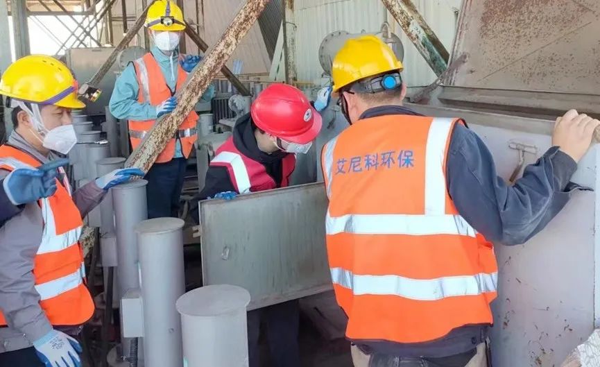
2. Structural Failures Identified During Field Inspection
In a site visit to evaluate the aging MEEP system on a 360m² sintering line, the technical team conducted a full walk-through inspection and system analysis. The following issues were identified:
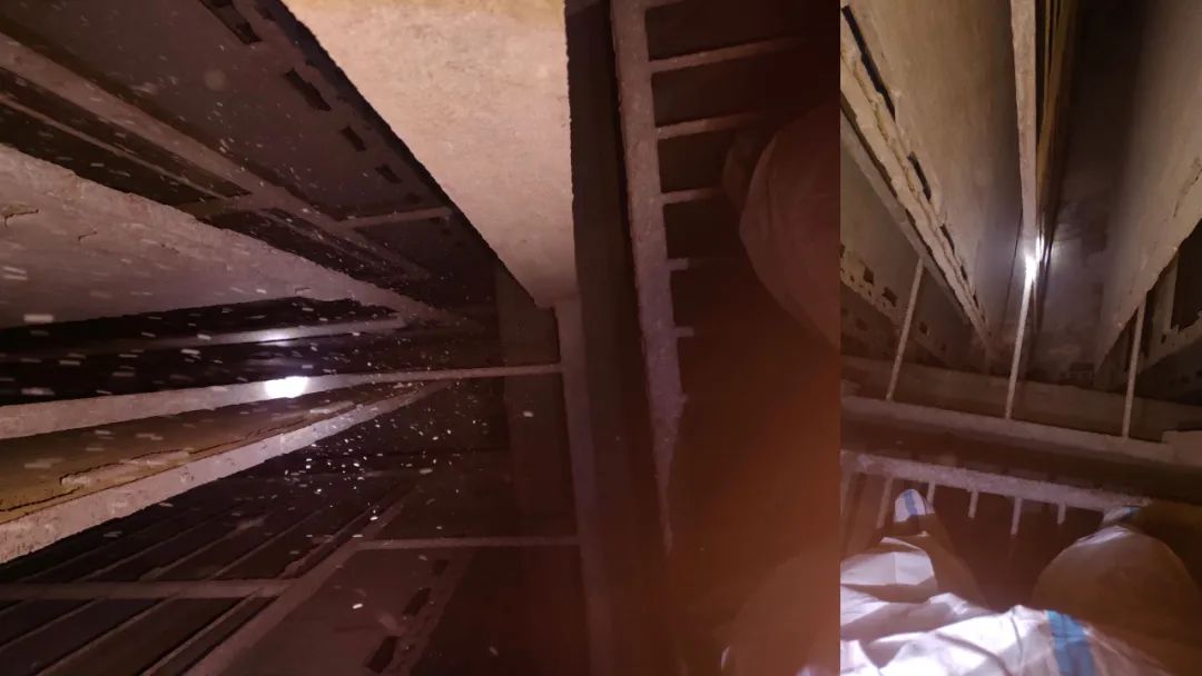
1. Electrode Plate Jamming and Structural Loss
- Several groups of moving electrodes in the first and second fields were jammed and unable to operate.
- Inconsistent spacing between discharge electrode and collecting plates limited voltage rise and field strength.
- Certain fields had missing collecting plates, reducing the effective collection area.
- Deformation of lower guide structures disrupted movement stability.
- Slack in the external drive chain caused desynchronization in plate motion.
2. Rapping System Malfunctions
- All ceramic shafts for the DE rapping system were fractured due to thermal cycling and material fatigue.
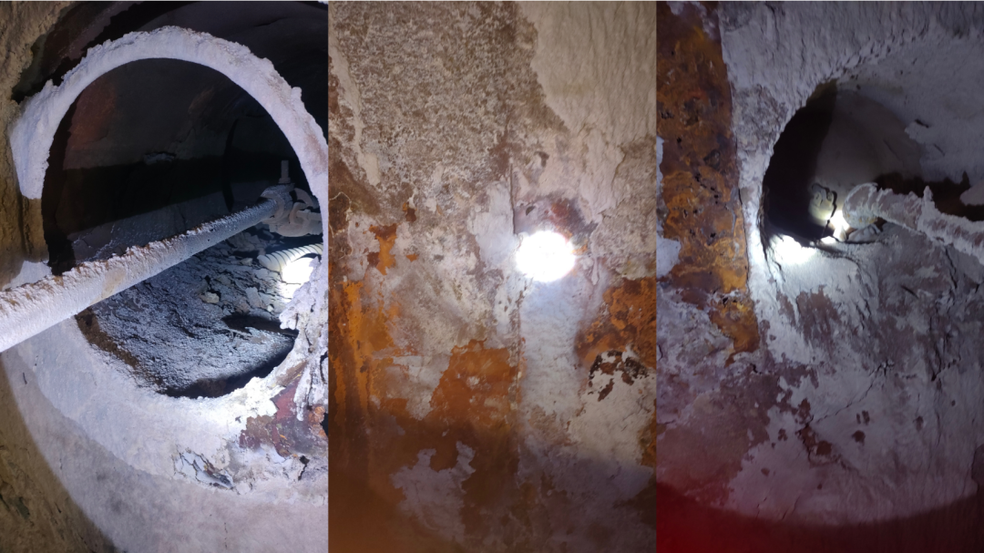
- Severe corrosion and air leakage in the rapping shaft heater box rendered it ineffective, accelerating wear on internal components.
- Most CP rapping clamps had fractured, and rust-induced cracking compromised structural integrity.
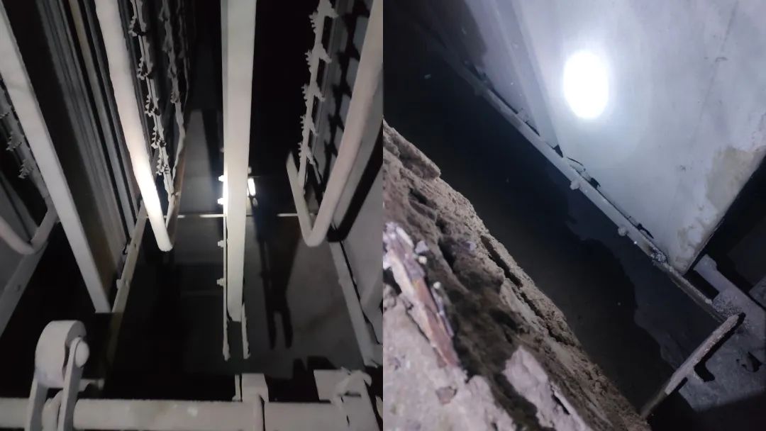
Several rapping devices experienced “overstroke” or cover detachment, presenting both performance and safety risks.
These findings highlighted the critical importance of mechanical alignment, rapping integrity, and structural continuity in maintaining long-term MEEP reliability.
3. Key Retrofit Areas and Execution Strategy
To address the issues and restore system functionality, the following measures were prioritized:
1. Collecting Plate Assembly Restoration
- Realigned and recalibrated guide structures to ensure smooth and symmetrical plate motion.
- Replaced all missing electrode plates to restore collection area and field uniformity.
- Retensioned and repaired the external drive chain to reestablish synchronized movement.
2. Rapping System Rehabilitation
- Replaced all damaged ceramic shafts and clamp assemblies.
- Repaired corrosion in the heater box to restore effective thermal insulation and reduce energy loss.
- Improved rapping force transmission by redesigning impact paths for enhanced cleaning performance.
3. Project Scheduling and Execution Under Constraints
- With only 30 days from order to site delivery and a 12-day installation window, the team implemented preassembly, parallel workflows, and early-stage technical coordination.
Senior engineers were dispatched ahead of installation to finalize scope, conduct technical briefings, and facilitate on-site efficiency during the compressed shutdown period.
4. Results and Post-Retrofit Performance
Following the completion of retrofit activities, the system was restarted and achieved stable operation within expected parameters. Key outcomes included:
- System voltage quickly returned to design levels.
- Electrode movement and rapping effectiveness were restored.
- Dust emissions stabilized within regulatory limits.
- System resistance decreased, and transformer loading returned to normal levels.
The end user reported a strong performance recovery and expressed satisfaction with the retrofit process and results.
5. Conclusion and Recommendations
In long-cycle MEEP systems, structural degradation is inevitable—but it does not need to compromise overall performance. Timely diagnostics and targeted retrofits can restore efficiency and extend the system’s service life.
As the moving electrode system plays a central role in the MEEP’s operation, maintaining motion integrity, precise alignment, and rapping coordination is essential. We recommend asset owners adopt a preventive maintenance strategy that includes:
- Regular structural inspections,
- Close monitoring of subtle changes in operating data (e.g., voltage rise time, rapping frequency, current patterns),
- And phased retrofit planning to avoid forced outages.
This article is based on a real-world project and is intended to support technical knowledge sharing in the dust collection and air pollution control industry. If you want learn more about the case study, please contact us intl.biz@eetc.cn